Here's the usual boiler plate:
1. Lethal voltages are present. If you are unfamiliar with working on equipment with high voltages STOP. Send the work to a qualified technician.
2. Unplug the AC when working on the radio.
3. With the AC unplugged, discharge the electrolytics to chassis before working around them.
It is assumed that the rig is lying upside-down with the back of the chassis closest to you
Definitions:
1. For simplicity the two (2) new 68 uF @ 450V radial electrolytic capacitors in the kit will be referred to in the text as "the right-hand" and "the left-hand" 68 uF caps.
2. The two (2) original 50 uF @ 350V insulated can-capacitors which are mounted on top of the chassis known as C-202 and C-203, will be referred to as "the original 50 uF can-caps".
3. The four terminals on the new multi-section can-cap will be referred to by their positions on a clock. The most forward (square symbol) will be "12 o'clock", the next terminal clockwise (triangle) will be "three o'clock", etc.
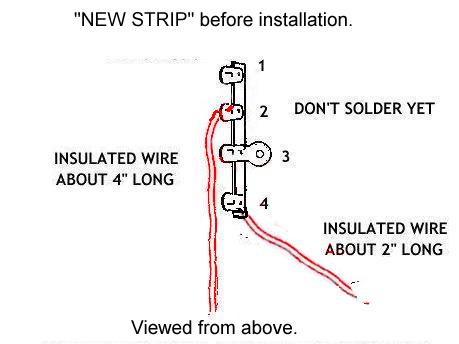
4. You will be adding a new four-lug terminal strip. It will be referred to as "the new strip"
5. Per the illustrations, the lugs of the new strip will be numbered 1 thru 4, starting with the lug furthest forward and then proceeding back toward you.
6. You will be attaching some components to an existing four-lug terminal strip that is located to the right of the multi-section capacitor. It will be referred to as "the right-hand strip".
Below is an illustration that shows the point in the reassembly process at which this instruction sheet begins:

The new multi-section can-cap has been installed and wires removed during the R&R have been reinstalled. There is one short red wire that originally ran from the 12 o'clock lug to a twist-tab on the rearmost original 50 uF can-cap. It will not be reinstalled. The 3-watt 220 ohm, 3-watt 33K ohm, and 5-watt 330 ohm resistors have been positioned in the correct terminals. The 3 o'clock and 6 o'clock terminals have been soldered, however the 9 o'clock and 12 o'clock terminals are left unsoldered for the time being. The 7 watt 100 ohm resistor, and the two (2) 3 watt 100K ohm resistors included in the kit will be installed later. We would also suggest leaving the terminals at 9-o'clock and 12 o'clock desoldered at this time.
The actual process of mounting the two 68 uF caps officially starts here. The original 50 uF @ can-caps are often left attached to the chassis for aesthetics, and because of the risk of damaging the band switch wafers when trying to remove them.
Looking at the diagram below, take the new terminal strip included in the kit. Note the offset position of the grounding lug, #3. Fasten a 4" long stranded insulated wire to lug #2, and a 2" insulated wire to lug #4 . Don't solder these connections yet.
The next step is to mount the new strip. It's held on by an existing screw, lock-washer, and nut. Here is a drawing showing the location of that hardware:
You may find it more convenient to replace the original screw with a longer one.
The following drawing shows the strip mounted to the underside of chassis, and the points of attachment for the two insulated wires installed in the last step. Do not solder either end of either wire yet. BE VERY CAREFUL WHEN WORKING AROUND THE BAND SWITCH AS ITS WAFERS ARE FRAGILE. 
You can go ahead and solder the 9-o'clock terminal now if you want to. Leads that will be soldered at that lug are:
1. Stranded wire from lug #2 of the new terminal strip.
2. Red wire from the auxiliary socket on the rear of the chassis.
3. Lead of the 5W 330 ohm power resistor (not shown).
4. Lead of the 3W 220 ohm resistor (not shown).
Do not solder either end of the wire that runs between lug #4 of the new strip to lug #1 of the right-hand strip.
The following step will require some work in fairly close proximity to the wafers of the band switch. Again, please use caution.
Slide a 68 uF cap between the band switch and the new strip as shown. This will be the "right-hand" 68 uF cap. The body of the capacitor should be as close to the chassis as possible, and to the left of the band switch. Slip the positive lead through lug #4 of the new strip and the negative lead through the terminal at 12 o'clock on the multi-section can-cap, but don't solder either one. Note the heavy red lines designating the positive lead.
The body of the other 68 uF cap (the "left-hand" 68 uF cap) will be placed between the plate-tuning capacitor and the power transformer as shown. The positive lead goes to lug #1 of the new strip , and the negative lead is attached to lug #2. Again, the heavy red line designates the positive lead.
Don't solder lugs #1 or #4 on the new strip yet, but you can solder #2. Attached to #2 lug are the following:
1. Negative lead from the "left-hand" 68 uF cap.
2. Stranded wire, other end of which is attached to 9 o'clock terminal on the multi-section cap.
Below is a pic shows how the 68 uFs caps actually look when in position. NOTE: Other components and wiring are removed for clarity in this photo.

For the next step refer to the drawing below:
Mount the 100 ohm 7W power resistor above the new strip with one lead in lug #1 and the other in lug #4 of the new terminal strip as shown.
Then, in lug #1 place the choke and capacitor leads (these you would have removed from the forward-most 50 uF can-cap during disassembly).
Per the Heathkit manual, don't wrap the leads from the choke and cap around the lug in a permanent fashion because you may be unhooking them to neutralize the final from time to time.
Go ahead and solder lug #1 on the new strip.
The leads attached to lug #1 will be:
1. The choke lead/capacitor lead(s),
2. The positive lead of the left-hand 68 uF cap by the transformer,
3 A lead from the 7 watt power resistor,
Go ahead and solder lug #4
In lug #4 you'll have:
1. A lead from the 100 ohm 7-watt resistor,
2. The positive lead of the right-hand 68 uF @ 450V electrolytic capacitor,
3. The insulated stranded wire that was installed in the first step.
There are two (2) 100K 3-watt resistors in the kit, and both will have a lead connected to the 12 o'clock terminal of the multi-section can (see below). 
After you have placed the leads of the two (2) 3 watt 100K resistors in the 12 o'clock terminal of the multi-section can-cap, that terminal should have the follow five (5) leads:
1. Two (2) leads from the 3 watt 100K resistors.
2. A lead from the 330 Ohm 5 watt resistor (not shown).
3. The negative lead from the right-hand 68 uF @ 450V cap.
4. The cloth-covered red wire from the power transformer.
You may go ahead and solder the 12 o'clock lug.
The opposite end of one of the 100K resistors goes to chassis. We prefer to put it back the original way, soldering it to lug #2 of the right-hand strip.
If the original heavy bare wire (not shown) from the rearmost original 50 uF can-cap is still attached to lug # 1 of the right-hand strip, remove it now and discard.
The remaining 100K resistor is run more of less parallel to the first, and the lead is placed in lug #1 of the right-hand strip. The stranded wire from lug #4 of the new strip should be placed in lug #1 of the right-hand strip at the same time.
You may now solder lug #1 of the right hand strip.
In lug # 1 you will now have:
1. The insulated stranded wire from lug #4 of the new strip.
2. A lead from one of the 3 watt 100 K resistors.
3. A lead from an existing diode rectifier.
Be careful that you don't overheat the diode rectifier on this same lug.
Check your work.
Check the resistances per the manual
Throw the switch and duck.
Shut off switch.
Scratch head.
Plug the rig in.
Throw the switch again.
Check the voltages. If possible, bring it up on a variac.